Hvac Condensate Pipe Size Calculator
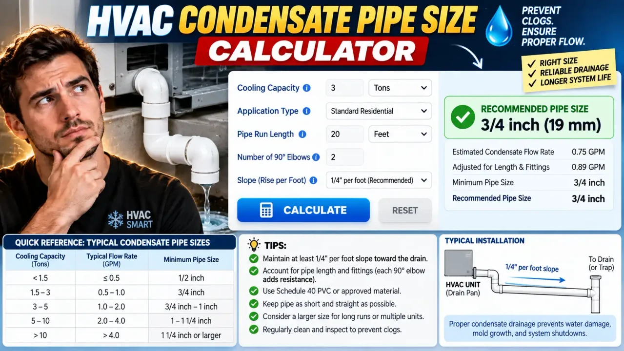
Use the Hvac Condensate Pipe Size Calculator to estimate minimum HVAC condensate drain pipe size from cooling capacity and drain pan outlet.
Please complete this field to continue.
Please complete this field to continue.
Please complete this field to continue.
Results
Hvac Condensate Pipe Size Calculator
TL;DR Summary
The Hvac Condensate Pipe Size Calculator helps estimate the minimum condensate drain pipe size using HVAC cooling capacity, whether equipment is manifolded, and the drain pan outlet size. It is a sizing aid based on the standard IMC condensate-drain sizing framework; local code adoption, equipment instructions, and project conditions still need to be checked. The tool's data-handling behavior is not specified here, so users should avoid entering sensitive information unless the page states how submitted data is handled.
About This Tool
The Hvac Condensate Pipe Size Calculator is designed to help HVAC professionals, contractors, designers, installers, inspectors, and building owners evaluate a condensate drain pipe size for cooling equipment. Condensate is the water produced when warm, moist air passes over a cooling coil and moisture collects on the coil or drain pan. The water must be carried safely away from the equipment.
Pipe sizing is important because a condensate drain that is too small, improperly reduced, or installed without the required slope can contribute to drainage problems. The applicable model mechanical and plumbing codes establish minimum requirements for condensate drainage. Under the International Mechanical Code framework, condensate drain piping generally cannot be smaller than 3/4 inch and cannot be reduced from the drain pan connection toward the disposal point. For manifolded drains serving more than one unit, the applicable sizing table uses total equipment capacity to determine the minimum pipe diameter.
This calculator is intended to make that sizing reference easier to apply. It separates the common single-unit minimum requirement from the capacity-based table used for manifolded condensate drainage. That distinction matters because the IMC table is specifically referenced when drains from multiple units are manifolded together.
What You Enter
The calculator uses a small number of inputs that directly affect the sizing decision.
- Manifolded drain: Choose whether condensate drains from more than one unit are combined into a common drain.
- Total cooling capacity: When drains are manifolded, enter the combined equipment capacity in tons of refrigeration. This is used to select the applicable capacity range.
- Drain pan outlet size: Enter the equipment's drain pan outlet size in inches. The final pipe recommendation cannot be smaller than the applicable connection requirement.
For a non-manifolded system, the capacity-based manifold table is not used as the controlling sizing table. The calculator instead applies the general minimum pipe-size and no-reduction principles and considers the entered drain pan outlet size.
What the Calculator Produces
The main result is the minimum recommended condensate pipe diameter under the selected calculation path. The result is shown in inches and also converted to millimeters for reference.
For manifolded systems, the capacity is compared with the following IMC sizing ranges: up to 20 tons requires at least 3/4 inch; over 20 through 40 tons requires 1 inch; over 40 through 90 tons requires 1-1/4 inches; over 90 through 125 tons requires 1-1/2 inches; and over 125 through 250 tons requires 2 inches. The model-code table also states that 1 inch equals 25.4 mm and one ton of refrigeration equals 3.517 kW.
The calculator also checks the selected drain pan outlet so that the calculated pipe size does not become smaller than that connection. This reflects the requirement that condensate drain piping not decrease in size from the drain pan connection to the disposal point.
How to Use
- Step 1: Identify whether the condensate drain serves one unit or combines drains from multiple units.
- Step 2: Select the appropriate manifolded or non-manifolded option.
- Step 3: Enter the drain pan outlet diameter in inches.
- Step 4: If the drain is manifolded, enter the total connected cooling capacity in tons of refrigeration.
- Step 5: Review the calculated minimum pipe diameter and the corresponding metric size.
- Step 6: Compare the result with the equipment manufacturer's installation instructions and the code adopted by the project jurisdiction before installation.
Technical Explanation and Formula
The sizing method is primarily a code-table lookup rather than a hydraulic pipe-flow equation. For a manifolded condensate system, the standard calculation can be represented as:
Required Table Size = pipe diameter specified by the applicable equipment-capacity range
| Total Equipment Capacity | Minimum Condensate Pipe Diameter |
|---|---|
| Up to 20 tons | 3/4 inch (19.05 mm) |
| Over 20 to 40 tons | 1 inch (25.4 mm) |
| Over 40 to 90 tons | 1-1/4 inches (31.75 mm) |
| Over 90 to 125 tons | 1-1/2 inches (38.1 mm) |
| Over 125 to 250 tons | 2 inches (50.8 mm) |
The calculator then applies the connection-size constraint:
Final Minimum Size = the larger of the applicable table size and the drain pan outlet size
For a non-manifolded system, the capacity table is not applied simply because an individual unit has a particular tonnage. Instead, the general minimum requirement and the drain pan connection are used. The basic constraint is:
Final Minimum Size = the larger of 3/4 inch and the drain pan outlet size
The capacity input is expressed in tons of refrigeration (TR). For metric reference, the code conversion is 1 ton = 3.517 kW. Pipe diameter is shown in inches, with millimeters calculated using 1 inch = 25.4 mm.
Worked Example
Suppose three cooling units share one condensate drain. Their combined cooling capacity is 60 tons, and the drain pan outlet feeding the common line is 1 inch.
A total capacity of 60 tons falls in the over 40 through 90 tons range. The capacity table therefore gives a minimum diameter of 1-1/4 inches. Because 1-1/4 inches is also larger than the 1-inch drain pan outlet, the calculator reports 1-1/4 inches (31.75 mm) as the minimum calculated size.
If the same common system had a 1-1/2-inch drain pan connection, the connection constraint would control, and the calculated minimum would be 1-1/2 inches rather than reducing the line to 1-1/4 inches.
Important Installation Considerations
Pipe diameter is only one part of condensate drainage design. The model-code provisions also address slope, disposal, materials, and maintenance. The IMC requires condensate piping to maintain a minimum horizontal slope in the direction of discharge of 1/8 unit vertical in 12 units horizontal, which is a 1% slope. The condensate must also be conveyed to an approved place of disposal and must not create a nuisance by discharging into areas such as streets or alleys.
Materials must be suitable for the installation. The code lists several permitted pipe and tubing materials, including PVC, CPVC, ABS, copper, polyethylene, polypropylene, and others, subject to the applicable requirements and pressure and temperature ratings. Equipment manufacturer instructions can also impose requirements for traps and other installation details.
Preset Examples / Quick Reference
| Manifolded Capacity | Table Minimum | Metric Equivalent |
|---|---|---|
| 10 TR | 3/4 inch | 19.05 mm |
| 30 TR | 1 inch | 25.4 mm |
| 60 TR | 1-1/4 inches | 31.75 mm |
| 100 TR | 1-1/2 inches | 38.1 mm |
| 150 TR | 2 inches | 50.8 mm |
Why Use This Hvac Condensate Pipe Size Calculator & How Our Calculator Beats the Competition
The practical benefit of this tool is that it puts the relevant capacity ranges and minimum-size checks into one calculation. It can be useful as a quick reference before reviewing drawings, equipment schedules, or installation details. It does not replace project-specific engineering or the code adopted by the authority having jurisdiction.
| Method | Ease of Use | Calculation Speed | Best For | Limitations |
|---|---|---|---|---|
| Toolhox Calculator | Simple inputs | Immediate calculation | Quick condensate pipe-size reference | Does not replace project-specific code review or engineering |
| Manual Calculation | Requires reference material | Depends on the user | Checking individual code requirements | More opportunity for lookup or arithmetic mistakes |
| Spreadsheet | Requires setup | Fast after setup | Repeated project calculations | Requires maintaining formulas and code tables |
| Professional Engineering Software | More involved | Depends on the application | Detailed system and project design | More inputs and a broader design scope may be required |
Assumptions and Limitations
- This calculator is a sizing reference based on the stated IMC condensate-drain framework.
- U.S. building codes are adopted and amended by jurisdictions. The applicable local code may differ from the model-code provisions used as the reference.
- The capacity table is specifically associated with manifolded condensate drains serving more than one unit.
- The calculator does not determine the complete condensate disposal system.
- It does not independently design traps, auxiliary drains, secondary protection, discharge locations, cleanouts, supports, fittings, or equipment-specific drainage arrangements.
- It does not determine whether a particular material or installation is approved at a specific project location.
- The result should be checked against the equipment manufacturer's instructions and the requirements enforced by the authority having jurisdiction.
- For unusual systems, large capacities, special equipment, or projects where water damage could create significant consequences, professional HVAC or plumbing review may be appropriate.
Use the result as a practical starting point, not as a substitute for the adopted mechanical or plumbing code, manufacturer instructions, construction documents, or professional judgment.