Hvac Return Air Duct Size Calculator By Btu
Use Hvac Return Air Duct Size Calculator By Btu to estimate return airflow, duct area, and equivalent duct dimensions from HVAC capacity for planning.
Please complete this field to continue.
Please complete this field to continue.
Please complete this field to continue.
Results
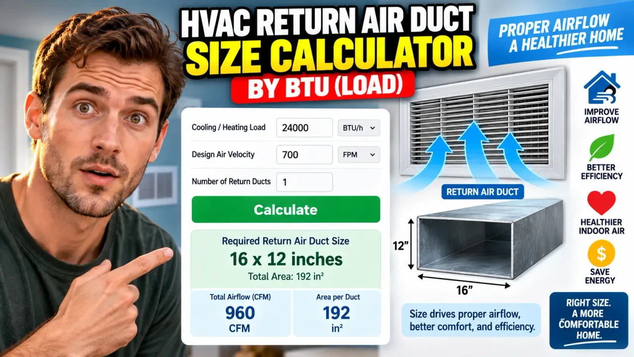
Hvac Return Air Duct Size Calculator By Btu
TL;DR Summary
The Hvac Return Air Duct Size Calculator By Btu estimates return-air airflow and the duct cross-sectional area from HVAC capacity in BTU/hr, using a selected CFM-per-ton factor and return-air velocity. It is a preliminary sizing estimate rather than a complete Manual D duct design, and the supplied tool information does not establish how user data is stored or transmitted, so avoid entering sensitive information.
About This Tool
The Hvac Return Air Duct Size Calculator By Btu is a preliminary HVAC sizing tool for estimating the airflow and approximate return duct size associated with a heating or cooling system capacity. Instead of starting with an airflow value in CFM, you enter the equipment capacity in BTU/hr. The calculator converts that capacity to tons, estimates the required airflow, and then converts the airflow into a required duct area based on the selected return-air velocity.
This can be useful when you are planning a residential HVAC project and want a quick starting point for return duct sizing. Homeowners, HVAC learners, contractors, remodelers, and other users can use the calculation to understand how equipment capacity, airflow, and duct area are related. It can also help when comparing different target velocities before a more complete duct design is performed.
The calculator uses three inputs. The first is HVAC Capacity (BTU/hr). BTU/hr is a measure of heating or cooling capacity. The second is Airflow per Ton, expressed in CFM per ton. The default selection is 400 CFM per ton because ACCA describes 400 CFM per ton as a common industry rule of thumb for getting into the general airflow range when detailed system design is not being performed. ACCA also notes that actual equipment airflow should be based on the selected equipment and its manufacturer performance information. :contentReference[oaicite:6]{index=6}
The third input is Target Return Duct Velocity, measured in feet per minute, or FPM. The calculator offers 500, 600, and 700 FPM. These values allow you to see how changing the target velocity changes the required duct area. A lower velocity requires a larger cross-sectional area for the same airflow. A higher velocity requires less area, but velocity is only one part of proper duct design.
What the Calculator Produces
The result includes the estimated system size in tons, estimated return airflow in CFM, required return duct area in square inches, an equivalent round duct diameter, an equivalent square duct size, and the target return velocity used in the calculation.
For example, consider a 36,000 BTU/hr HVAC system with the default 400 CFM per ton setting. The equipment capacity converts to 3 tons because 36,000 divided by 12,000 equals 3. At 400 CFM per ton, the estimated airflow is 1,200 CFM. If the selected return velocity is 700 FPM, the required cross-sectional area is about 246.9 square inches. The equivalent round diameter is about 17.7 inches. These are mathematical equivalents, not a recommendation to purchase a specific manufactured duct size.
The same 1,200 CFM airflow produces a different area if a lower velocity is selected. At 600 FPM, the required area is 288 square inches. At 500 FPM, it is 345.6 square inches. This shows why duct size cannot be determined from BTU capacity alone without making an airflow and velocity assumption.
How to Use
- Step 1: Enter the HVAC system's nominal capacity in BTU/hr, such as 36,000 BTU/hr for a nominal 3-ton system.
- Step 2: Select the CFM-per-ton factor you want to use. The calculator starts with 400 CFM/ton as the general rule-of-thumb setting.
- Step 3: Select the target return duct velocity of 500, 600, or 700 FPM.
- Step 4: Review the estimated return airflow and required duct area.
- Step 5: Use the equivalent round diameter or square dimensions as a preliminary reference, then verify the final duct design using the equipment data and an appropriate duct-design method.
Technical Explanation and Formula
The calculation uses a simple airflow and velocity relationship. It is important to understand that this is a sizing shortcut, not a complete ACCA Manual D design. ACCA Manual D covers duct-system design using airflow, blower performance, available static pressure, friction rate, duct material, fitting effects, and other design factors. :contentReference[oaicite:7]{index=7}
Step 1: Convert BTU/hr to nominal tons.
Tons = BTU/hr ÷ 12,000
Here, BTU/hr is the entered HVAC capacity and 12,000 BTU/hr represents one nominal refrigeration ton.
Step 2: Estimate return airflow.
CFM = Tons × CFM per Ton
CFM means cubic feet per minute. The CFM-per-ton value is selected by the user. The default is 400 CFM/ton. ACCA's current educational guidance describes 400 CFM per ton as a common rule of thumb, while also emphasizing that actual system airflow should be determined from equipment and system design information. :contentReference[oaicite:8]{index=8}
Step 3: Calculate duct area.
Duct Area (sq ft) = CFM ÷ Target Velocity (FPM)
To express the result in square inches:
Duct Area (sq in) = CFM × 144 ÷ Target Velocity
The number 144 converts square feet to square inches because one square foot contains 144 square inches.
Step 4: Calculate an equivalent round duct diameter.
Diameter = √(4 × Area ÷ π)
The area is in square inches and the resulting diameter is in inches.
Step 5: Calculate an equivalent square size.
Square Side = √Area
This produces a mathematical square with the same cross-sectional area. Actual rectangular duct selections may use different dimensions because installation space, aspect ratio, fittings, material, and pressure loss all matter.
Worked Example
| Input or Result | Example |
|---|---|
| HVAC capacity | 36,000 BTU/hr |
| Nominal capacity | 3 tons |
| Airflow factor | 400 CFM/ton |
| Estimated airflow | 1,200 CFM |
| Target return velocity | 700 FPM |
| Required duct area | 246.9 sq in |
| Equivalent round diameter | 17.7 in |
| Equivalent square size | 15.7 x 15.7 in |
This example demonstrates the mathematical relationship only. It does not mean that a 17.7-inch round duct or a 15.7-by-15.7-inch duct is automatically the correct installed size. Standard duct sizes, actual airflow, duct length, fittings, filter resistance, static pressure, material, and installation conditions can change the final design.
Why BTU Capacity Does Not Tell the Whole Story
BTU capacity is a useful starting point, but it is not a complete duct-design input. ACCA explains that proper duct design involves system operating conditions and blower performance. Manual D provides detailed residential duct-sizing procedures and includes friction charts, fitting equivalent lengths, velocity guidance, and other design information. :contentReference[oaicite:9]{index=9}
ACCA also notes that a system's required airflow may differ from a simple 400 CFM-per-ton rule of thumb. Recent ACCA guidance describes 400 CFM per ton as a common benchmark while emphasizing that actual airflow depends on the equipment and the building's design requirements. :contentReference[oaicite:10]{index=10}
For this reason, the calculator is best used for preliminary planning, education, and a quick comparison of airflow and duct-area assumptions. It should not replace a complete load calculation, equipment selection, blower-performance review, or duct-system design.
Why Use This Hvac Return Air Duct Size Calculator By Btu & How Our Calculator Beats the Competition
The practical advantage of this calculator is that it connects a familiar HVAC capacity value, BTU/hr, to airflow and duct area without requiring the user to begin with CFM. It is useful for a first-pass estimate, while more detailed methods remain appropriate for final system design.
| Method | Ease of Use | Calculation Speed | Best For | Limitations |
|---|---|---|---|---|
| Toolhox Calculator | Simple inputs | Immediate calculation | Preliminary BTU-to-airflow and duct-area estimates | Does not perform a complete Manual D design |
| Manual Calculation | Requires formula knowledge | Depends on the user | Understanding the underlying math | Easy to make unit or arithmetic errors |
| Spreadsheet Calculation | Moderate | Fast after setup | Custom worksheets and repeated scenarios | Requires formulas and correct setup |
| Professional Engineering Software | More involved | Depends on software and model | Detailed HVAC and duct-system design | More inputs and design knowledge are required |
Assumptions and Limitations
- The calculator treats 12,000 BTU/hr as one nominal ton.
- The estimated airflow depends directly on the selected CFM-per-ton factor.
- The default 400 CFM/ton value is a rule-of-thumb starting point, not a universal equipment requirement.
- The duct-area calculation assumes the selected target velocity is appropriate for the preliminary estimate.
- The calculated round diameter and square dimensions are mathematical equivalents and are not automatically standard stock duct sizes.
- The calculation does not determine duct friction rate, external static pressure, equivalent length, fitting losses, blower performance, filter pressure drop, duct leakage, insulation, or room-by-room airflow requirements.
- The calculation does not perform an ACCA Manual J load calculation or a complete ACCA Manual D duct design.
- Actual equipment airflow should be checked against manufacturer performance data.
- Final duct sizing should account for the entire return path, including grilles, filters, fittings, branches, trunks, and available static pressure.
ACCA identifies Manual J for residential load calculations, Manual S for equipment selection, and Manual D for residential duct design. These methods work together rather than treating BTU capacity alone as sufficient for a final duct decision. :contentReference[oaicite:11]{index=11}
Use this calculator for a preliminary estimate. For a new installation, major replacement, difficult retrofit, comfort problem, or system where pressure and airflow are critical, the result should be reviewed as part of a proper HVAC design rather than used alone.