Cable Voltage Drop Calculator Online
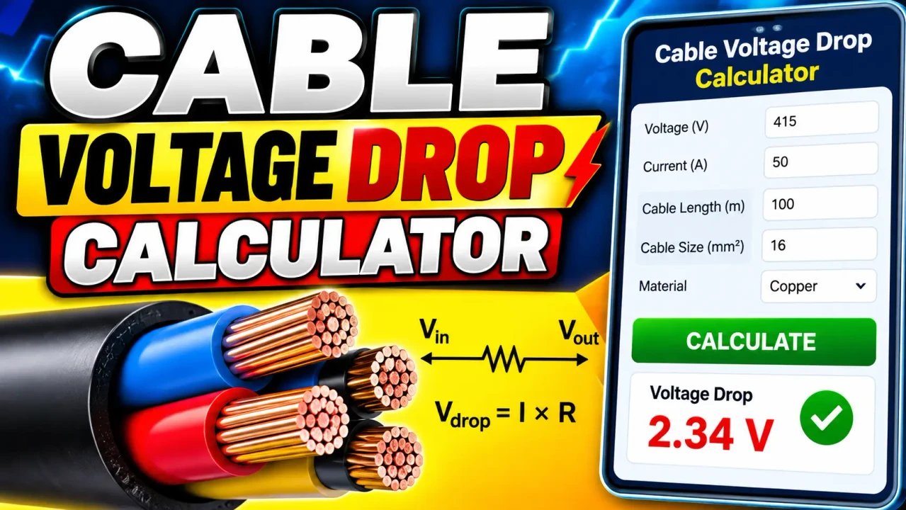
Use Cable Voltage Drop Calculator to estimate voltage loss from cable length, load current, conductor area, material, and circuit type, plus load-end voltage.
Please complete this field to continue.
Please complete this field to continue.
Please complete this field to continue.
Please complete this field to continue.
Please complete this field to continue.
Please complete this field to continue.
Please complete this field to continue.
Results
cable voltage drop calculator
TL;DR Summary
The cable voltage drop calculator estimates voltage loss in a cable from system voltage, load current, one-way cable length, conductor area, conductor material, and circuit type. It is a general engineering estimate based on conductor resistance and should not be used by itself as a final wiring, ampacity, or code-compliance decision; the tool's privacy behavior is not specified by the supplied information.
What This Cable Voltage Drop Calculator Does
The cable voltage drop calculator helps estimate how much voltage is lost as electrical current travels through a cable. Every conductor has electrical resistance. When current flows through that resistance, some of the available voltage is lost along the cable. The longer the cable, the higher the current, and the smaller the conductor cross-sectional area, the greater the voltage drop will generally be.
This tool is intended for quick planning and checking of basic cable voltage drop. It can be useful for electricians, electrical technicians, engineers, installers, students, maintenance personnel, and anyone who needs a first-pass estimate of cable voltage loss.
The calculator accepts the system voltage, load current, one-way cable length, length unit, conductor cross-sectional area, conductor material, and circuit type. Length can be entered in feet or meters. The conductor area is entered in square millimeters. Copper and aluminum conductors are supported. Circuit options include DC two-wire, AC single-phase, and AC three-phase.
The main results are the estimated voltage drop in volts, voltage drop as a percentage of the system voltage, estimated voltage at the load end, and the calculated one-way conductor resistance.
What Inputs Do I Need?
- System voltage: Enter the nominal voltage supplied to the circuit, such as 120 V, 240 V, or another applicable system voltage.
- Load current: Enter the current carried by the cable in amperes.
- One-way cable length: Enter the physical distance from the source to the load. Do not enter the round-trip distance.
- Length unit: Select feet or meters.
- Conductor cross-sectional area: Enter the conductor area in square millimeters. This is the conductive metal area, not the outside diameter of the complete cable.
- Conductor material: Select copper or aluminum.
- Circuit type: Select DC two-wire, AC single-phase, or AC three-phase.
The calculator does not ask for cable insulation type, installation method, ambient temperature, conduit type, number of current-carrying conductors, or ampacity. Those factors can matter when selecting a compliant conductor, but they are outside the basic voltage-drop calculation provided here.
How to Use the Cable Voltage Drop Calculator
- Step 1: Enter the nominal system voltage in volts.
- Step 2: Enter the load current in amperes.
- Step 3: Enter the one-way distance from the power source to the load and select feet or meters.
- Step 4: Enter the conductor cross-sectional area in square millimeters.
- Step 5: Select copper or aluminum as the conductor material.
- Step 6: Select DC two-wire, AC single-phase, or AC three-phase.
- Step 7: Review the voltage drop in volts, voltage drop percentage, load-end voltage, and calculated conductor resistance.
Technical Explanation and Formula
The basic resistance of a conductor is calculated from its material resistivity, length, and cross-sectional area:
R = ρ × L / A
Where:
- R = conductor resistance in ohms (Ω)
- ρ = material resistivity in ohm-meters (Ω·m)
- L = one-way conductor length in meters
- A = conductor cross-sectional area in square meters (m²)
The calculator converts feet to meters when necessary and converts the entered square-millimeter area to square meters before applying the resistance formula. The approximate 20°C resistivity values used are 1.724 × 10⁻⁸ Ω·m for copper and 2.65 × 10⁻⁸ Ω·m for aluminum. NIST conductor references provide resistivity and conductivity data used for electrical wire calculations. :contentReference[oaicite:2]{index=2}
For a DC two-wire or AC single-phase circuit, the basic voltage-drop relationship used here is:
Vd = 2 × I × R
The factor of 2 represents the outgoing and returning conductor paths. For a balanced three-phase circuit, the simplified resistive relationship is:
Vd = √3 × I × R
Fluke documents these common simplified voltage-drop equations, including the 2 × K × L × I / A form for single-phase circuits and the 1.73 × K × L × I / A form for three-phase circuits. :contentReference[oaicite:3]{index=3}
After voltage drop is calculated, the percentage is found with:
Voltage Drop % = (Voltage Drop / System Voltage) × 100
The estimated voltage available at the load is then:
Load-End Voltage = System Voltage − Voltage Drop
These equations are a simplified resistive model. More detailed AC cable calculations can also include conductor reactance and load power factor. Southwire's technical guide describes AC voltage-drop calculations using both resistance and reactance and notes that power factor can affect the result. :contentReference[oaicite:4]{index=4}
Worked Example
Suppose a 120 V single-phase circuit carries 15 A through a 100 ft copper cable with a conductor area of 2.5 mm².
| Input | Example Value |
|---|---|
| System voltage | 120 V |
| Load current | 15 A |
| One-way length | 100 ft |
| Conductor area | 2.5 mm² |
| Material | Copper |
| Circuit | AC single-phase |
Converting 100 ft gives approximately 30.48 m. Using the copper resistivity value, the estimated one-way conductor resistance is about 0.2102 Ω. The simplified single-phase calculation gives a voltage drop of about 6.31 V. That is approximately 5.25% of 120 V, leaving an estimated 113.69 V at the load.
This example shows why cable length, current, conductor size, and material all matter. A longer run or higher load current increases the voltage drop. Increasing conductor area generally reduces resistance and therefore reduces voltage drop.
Understanding the Results
Voltage Drop tells you the estimated number of volts lost along the circuit. Voltage Drop Percentage puts that loss into context by comparing it with the source voltage. Load-End Voltage estimates the voltage remaining at the load under the stated conditions. One-Way Conductor Resistance shows the calculated resistance of one conductor over the entered one-way distance.
A low voltage-drop percentage does not automatically mean that a cable is safe or code compliant. Conductor ampacity, overcurrent protection, insulation rating, installation conditions, termination ratings, ambient temperature, conductor grouping, and other requirements must be evaluated separately.
Why Use This cable voltage drop calculator & How Our Calculator Compares With Other Methods
| Method | Ease of Use | Calculation Speed | Best For | Limitations |
|---|---|---|---|---|
| Toolhox Cable Voltage Drop Calculator | Enter the core electrical values and review calculated results | Immediate calculation from entered values | Quick voltage-drop estimates and learning | Uses a simplified resistive model and does not replace full cable design |
| Manual Calculation | Requires formula setup and unit conversions | Depends on the person performing the calculation | Learning and checking individual calculations | More opportunity for arithmetic or unit-conversion errors |
| Spreadsheet | Requires a prepared worksheet | Fast after the spreadsheet is configured | Repeated calculations and project worksheets | Formula and input errors can be carried into later results |
| Professional Engineering Software | Usually requires more setup and domain knowledge | Depends on the software and model | Detailed electrical design and engineering studies | May require detailed project, cable, installation, and system data |
The practical purpose of this calculator is to provide a focused first-pass voltage-drop calculation without requiring a full electrical design model. It is not intended to replace professional engineering software where detailed AC impedance, installation configuration, temperature, harmonics, multiple circuit segments, or other system effects must be considered.
Voltage Drop and U.S. Electrical Practice
Voltage drop is an important consideration in U.S. electrical design. NFPA 70, the National Electrical Code, contains voltage-drop guidance in informational notes associated with branch circuits and feeders. Public NFPA material describes 3% branch-circuit voltage drop and 5% maximum total feeder-plus-branch voltage drop as providing reasonable efficiency of operation. These statements are informational guidance rather than a universal statement that every installation must meet exactly those percentages, and the edition adopted by an authority having jurisdiction can vary. :contentReference[oaicite:5]{index=5}
NFPA identifies the 2026 edition of NFPA 70 as a current publication, but the applicable edition and local amendments depend on the installation's jurisdiction. :contentReference[oaicite:6]{index=6}
Assumptions and Limitations
- The material resistivity values represent approximately 20°C conductor conditions.
- The cable length entered is one-way distance from the source to the load.
- DC two-wire and AC single-phase calculations use a two-conductor path.
- The three-phase calculation uses the standard balanced three-phase √3 relationship.
- The calculation treats conductor resistance as the primary source of voltage drop.
- The simplified model does not separately calculate AC conductor reactance.
- The simplified model does not use load power factor.
- The calculation does not determine conductor ampacity or required overcurrent protection.
- The calculation does not account for every installation-specific temperature or wiring condition.
- The result is an estimate and should not be treated as a complete electrical design or code-compliance determination.
For long AC runs, motors, transformers, power electronics, high-current systems, or installations where exact voltage regulation matters, a more detailed calculation using conductor impedance, operating temperature, power factor, installation configuration, and the applicable electrical code may be appropriate. Southwire's published technical guidance illustrates why resistance, reactance, and power factor can become important in detailed AC voltage-drop work. :contentReference[oaicite:7]{index=7}
Users should also check the electrical requirements applicable to their locati:contentReference[oaicite:8]{index=8} the state and local level, so a general voltage-drop calculation should not be treated as proof that an installation meets every local requirement. For safety-critical or regulated installations, qualified electrical design and inspection should be used alongside the calculator.