Zener Diode Voltage Regulator Calculator Tool Use
Use the Zener Diode Voltage Regulator Calculator Tool to estimate series resistor limits, zener current, and power for a basic shunt voltage regulator design.
Please complete this field to continue.
Please complete this field to continue.
Please complete this field to continue.
Please complete this field to continue.
Please complete this field to continue.
Please complete this field to continue.
Please complete this field to continue.
Results
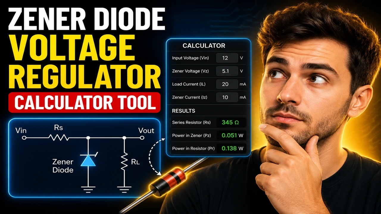
Zener Diode Voltage Regulator Calculator Tool
TL;DR Summary
The Zener Diode Voltage Regulator Calculator Tool estimates the allowable series-resistor range, regulated output voltage, Zener current, and power for a basic Zener shunt regulator. It is a design estimate based on idealized Zener-regulator relationships and does not replace component datasheet checks or engineering review; the supplied tool information does not establish a specific privacy or data-storage policy.
About This Tool
The Zener Diode Voltage Regulator Calculator Tool is designed for basic DC Zener diode shunt-regulator calculations. A simple Zener regulator uses a series resistor to limit current from the input supply and a Zener diode connected across the load. When the Zener is operating in its breakdown region, the voltage across the load is approximately the Zener voltage.
This type of calculation is useful when you need to estimate a suitable resistor range for a low-power regulated voltage rail. It can help electronics students, hobbyists, technicians, and engineers check the basic operating conditions of a Zener regulator before selecting actual components.
The calculator uses seven main inputs. You enter the minimum and maximum input voltage, the nominal Zener voltage, the minimum and maximum load current, the minimum Zener current required for regulation, and the maximum power allowed for the Zener diode. Voltages are entered in volts, currents in milliamps, and Zener power in watts.
The minimum and maximum input voltages matter because the Zener current changes as the supply voltage changes. The load-current range also matters because current supplied through the series resistor is divided between the load and the Zener. At high load current, enough current must still remain in the Zener to keep it in its intended regulation region.
The calculator therefore determines two important resistor limits. The maximum allowable series resistance is controlled by the lowest input voltage and highest load current. If the resistance is too high under this condition, the current left for the Zener may fall below the required minimum. The minimum allowable resistance is controlled by the highest input voltage and lowest load current. If the resistance is too low, excessive current can flow through the Zener and create excessive Zener power.
How to Use
- Step 1: Enter the minimum and maximum DC input voltage that the regulator is expected to receive.
- Step 2: Enter the Zener diode's nominal voltage in volts.
- Step 3: Enter the minimum and maximum load current in milliamps. Use 0 mA for minimum load current when a no-load condition is part of the design.
- Step 4: Enter the minimum Zener current needed for the selected diode to remain in the intended regulation region. Use the component datasheet when determining this value.
- Step 5: Enter the maximum Zener power that the design is allowed to dissipate. This should reflect the selected diode's applicable power rating and design margin.
- Step 6: Review the calculated minimum and maximum series-resistance limits. A feasible design requires the minimum resistance to be no greater than the maximum resistance.
- Step 7: Check the calculated Zener current and resistor power against the actual component datasheets, tolerances, temperature conditions, and intended operating environment before building the circuit.
Technical Explanation and Formula
The standard current relationship for a simple Zener shunt regulator is:
IR = IZ + IL
where IR is the current through the series resistor in amperes, IZ is Zener current in amperes, and IL is load current in amperes.
The basic voltage relationship is:
VIN = VZ + IRRS
where VIN is input voltage in volts, VZ is Zener voltage in volts, IR is resistor current in amperes, and RS is the series resistance in ohms.
For the lowest input voltage and highest load current, the series resistor must be small enough to maintain the required minimum Zener current:
RS,max = (VIN,min − VZ) / (IZ,min + IL,max)
For the highest input voltage and minimum load current, the Zener can receive its highest current. The calculator uses the entered maximum Zener power to determine the corresponding maximum permitted Zener current:
IZ,max = PZ,max / VZ
The minimum series resistance is then:
RS,min = (VIN,max − VZ) / (IZ,max + IL,min)
The basic design is feasible when:
RS,min ≤ RS,max
These equations represent the standard simplified design method for a Zener shunt regulator. Manufacturer guidance emphasizes that the actual Zener must remain within its specified operating-current range and power rating. Zener voltage also varies with current, temperature, and the diode's dynamic impedance, so the nominal Zener voltage should not be treated as an exact constant under every operating condition. :contentReference[oaicite:3]{index=3}
Worked Example
Consider a regulator with a 12 V minimum input, 15 V maximum input, a 5.1 V Zener, a 0 to 20 mA load range, a 5 mA minimum Zener current, and a 0.5 W maximum Zener power limit.
The maximum permitted Zener current from the power limit is:
IZ,max = 0.5 W / 5.1 V ≈ 98.04 mA
The maximum series resistance is:
RS,max = (12 − 5.1) / (0.005 + 0.020) = 276 Ω
The minimum series resistance is approximately:
RS,min = (15 − 5.1) / 0.09804 ≈ 100.98 Ω
Therefore, the simplified calculation gives an allowable resistance range of about 101 Ω to 276 Ω. This does not mean that every resistor in that range is automatically suitable. Actual resistor tolerance, Zener tolerance, temperature, power rating, and the diode's specified test conditions should be checked before selecting a production component.
Quick Reference
| Quantity | Unit | Purpose |
|---|---|---|
| Minimum input voltage | V | Sets the low-supply operating condition. |
| Maximum input voltage | V | Sets the high-supply operating condition. |
| Zener voltage | V | Approximate regulated output voltage. |
| Load current | mA | Determines how much resistor current goes to the load. |
| Minimum Zener current | mA | Helps maintain operation in the intended Zener region. |
| Maximum Zener power | W | Limits allowable Zener dissipation. |
Why Use This Zener Diode Voltage Regulator Calculator Tool & How Our Calculator Beats the Competition
The practical value of this calculator is that it puts the main worst-case checks into one calculation. It does not claim to replace a datasheet, circuit simulator, or engineering design review.
| Method | Ease of Use | Calculation Speed | Best For | Limitations |
|---|---|---|---|---|
| Toolhox Calculator | Enter the main regulator limits directly. | Immediate calculation from the supplied inputs. | Basic resistor-range and worst-case checks. | Uses a simplified model and does not select or validate a specific diode. |
| Manual Calculation | Requires more arithmetic. | Depends on the person doing the calculation. | Learning the equations and checking individual cases. | More opportunity for arithmetic or setup errors. |
| Spreadsheet | Requires a prepared worksheet. | Fast after the spreadsheet is built. | Repeated calculations and custom design studies. | Formula setup and maintenance are the user's responsibility. |
| Professional Engineering Software | Usually requires more setup. | Depends on the model and simulation. | Detailed circuit analysis and broader design verification. | More detailed than needed for a simple first-pass calculation. |
Assumptions and Limitations
This calculator treats the Zener voltage as the nominal regulated voltage and uses a simplified constant-voltage Zener model. Real Zener diodes have a voltage-current characteristic rather than a perfectly fixed voltage. Their voltage can change with operating current, temperature, tolerance, and dynamic resistance.
The calculation also uses the supplied minimum and maximum input voltages and load currents as design boundaries. It does not automatically account for input-voltage transients, resistor tolerance, Zener-voltage tolerance, temperature coefficient, dynamic impedance, thermal derating, PCB temperature, or a particular manufacturer's datasheet test current.
The maximum Zener power input should be selected carefully. A device's published power rating is not automatically the same as the preferred continuous design dissipation. The actual component datasheet and thermal conditions should be used when selecting the Zener and resistor.
The result is therefore a preliminary engineering estimate, not a guarantee that a physical circuit will regulate at exactly the displayed voltage. A production design or safety-critical circuit should receive appropriate component-level and system-level review.
For a more detailed design, manufacturer data should be checked for the selected Zener's minimum and maximum operating current, nominal voltage tolerance, test conditions, dynamic resistance, temperature behavior, and power derating. ON Semiconductor's Zener handbook specifically notes that output variation depends on input voltage, load current, temperature, and Zener impedance. :contentReference[oaicite:4]{index=4}