Hvac System Zoning Requirements Calculator Online
Use Hvac System Zoning Requirements Calculator to estimate zone thermostats, dampers, indoor units, valves, and controller needs for an HVAC zoning design.
Please complete this field to continue.
Please complete this field to continue.
Results
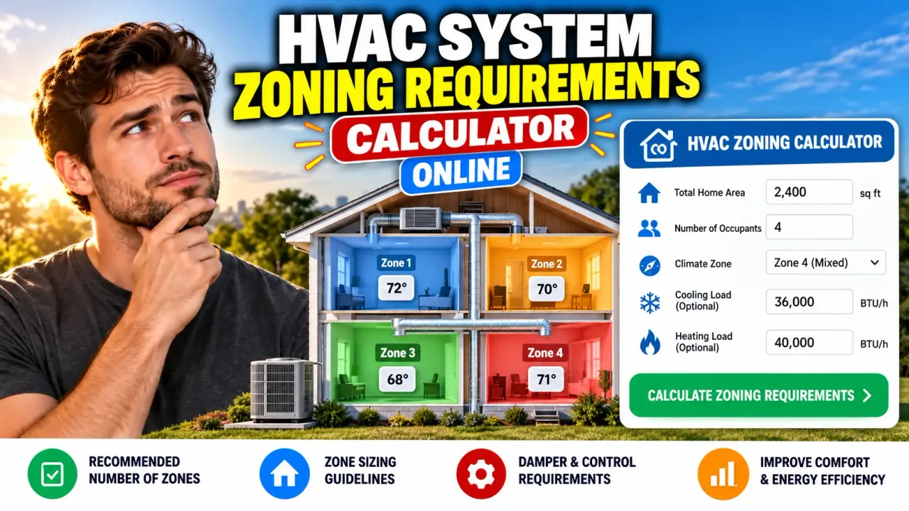
Hvac System Zoning Requirements Calculator
TL;DR Summary
The Hvac System Zoning Requirements Calculator estimates the basic number of zone controls and major zoning components needed from the selected HVAC zoning method and number of zones. It is a planning estimate rather than a complete HVAC design, and the supplied tool information does not establish a specific privacy or data-storage policy.
About This Tool
The Hvac System Zoning Requirements Calculator is a planning tool for estimating the basic component requirements of a multi-zone HVAC system. It is designed for homeowners, HVAC contractors, installers, building planners, and anyone reviewing a preliminary zoning concept.
HVAC zoning divides a building into separate areas that can be controlled independently. Instead of treating the entire building as one temperature area, a zoning system can manage different parts of the building according to their individual comfort needs. Common examples include separating upstairs and downstairs areas, grouping bedrooms separately from living areas, or creating different control areas in a large home.
The calculator starts with two inputs: the HVAC zoning method and the number of zones. The zoning method can be ducted HVAC with zone dampers, ductless multi-split, or hydronic or water-based zoning. The number of zones represents the independently controlled areas that the proposed system is intended to serve.
For ducted HVAC zoning, the calculator uses one motorized zone damper per zone as a basic planning minimum. It also identifies the number of temperature control points and gives a controller-capacity target based on the number of zones. Actual duct systems may require more than one damper for a zone when multiple duct branches serve the same controlled area.
For ductless multi-split zoning, the calculator uses one indoor unit per independently controlled zone as the basic planning relationship. Actual equipment selection depends on the manufacturer's system architecture, indoor-unit capacity, outdoor-unit capacity, refrigerant piping, control compatibility, and the heating and cooling loads of each zone.
For hydronic zoning, the calculator uses one independently controlled zone valve or actuator per zone as the basic planning relationship. A real hydronic design may use different valve arrangements, circulators, manifolds, zone controls, or other equipment depending on the heating or cooling system.
What Does the Calculator Estimate?
The main output is the number of basic zone-level controls required for the selected number of zones. It also provides a controller-capacity target and a method-specific component estimate.
| Zoning Method | Basic Component Estimate | Planning Relationship |
|---|---|---|
| Ducted HVAC with zone dampers | Motorized zone dampers | At least 1 damper per zone |
| Ductless multi-split | Indoor units | 1 independently controlled indoor unit per zone |
| Hydronic / water-based zoning | Zone valves or actuators | 1 independently controlled circuit per zone |
How to Use
- Step 1: Select the HVAC zoning method that matches the proposed system: ducted zone dampers, ductless multi-split, or hydronic zoning.
- Step 2: Enter the number of independently controlled zones in the building. Use two or more zones for a zoning plan.
- Step 3: Review the calculated zone controls and method-specific component quantity.
- Step 4: Use the result as a preliminary planning reference and verify equipment, load, airflow or water-flow, control, and installation requirements with the actual system design.
Technical Explanation and Formula
The calculator uses simple zone-count relationships for preliminary planning. It does not claim to perform a full Manual J load calculation, Manual D duct design, equipment selection, hydronic balancing calculation, or manufacturer-specific control configuration.
The core planning formula is:
Minimum zone-level controls = Number of zones
For a ducted damper system:
Minimum motorized zone dampers = Number of zones
For a ductless multi-split system:
Planning indoor units = Number of zones
For hydronic zoning:
Planning zone valves or actuators = Number of zones
The variable N is the number of independently controlled zones. N is a whole number of 2 or more. The calculator does not apply a universal airflow, heating-load, cooling-load, valve-sizing, damper-sizing, or equipment-capacity factor because those values depend on the building and selected equipment.
Worked Example
Suppose a home is divided into three ducted HVAC zones: an upstairs zone, a downstairs living-area zone, and a bedroom zone.
With N = 3:
Minimum zone temperature controls = 3
Minimum motorized zone dampers = 3
Controller capacity target = 3 zones
This is a planning result. It does not mean that every three-zone installation can use the same controller, damper size, duct arrangement, or HVAC equipment. The final design must match the actual equipment and zone loads.
Why Zone Count Alone Is Not Enough
Counting zones is only the starting point for HVAC zoning. A proper design also considers the heating and cooling load of each zone, the airflow required by the equipment, duct design, equipment operating range, control strategy, and what happens when only one or a small number of zones are calling for conditioning.
ACCA's residential zoning guidance specifically addresses zone load calculations, zone damper systems, bypass-path design, excess-air management, duct design, balancing, and equipment selection. ACCA also describes Manual Zr as a residential zoning standard compatible with Manual J procedures. :contentReference[oaicite:1]{index=1}
For example, a three-zone system does not automatically mean that three equal-size dampers are appropriate. Damper size depends on the duct and required airflow. Likewise, a controller must be compatible with the HVAC equipment and support the required number of zones.
Preset Examples and Quick Reference
| Zones | Temperature Controls | Ducted Dampers* | Ductless Indoor Units* | Hydronic Valves* |
|---|---|---|---|---|
| 2 | 2 | 2 | 2 | 2 |
| 3 | 3 | 3 | 3 | 3 |
| 4 | 4 | 4 | 4 | 4 |
| 5 | 5 | 5 | 5 | 5 |
*The component columns show the calculator's basic planning relationship, not a final equipment schedule.
Manufacturer documentation also illustrates why component selection must be checked against the actual zoning platform. For example, a Resideo TrueZONE worksheet specifies at least one damper per zone and one thermostat per zone for its particular product family, while its control panels have different zone capacities. :contentReference[oaicite:2]{index=2}
Why Use This Hvac System Zoning Requirements Calculator & How Our Calculator Beats the Competition
| Method | Ease of Use | Calculation Speed | Best For | Limitations |
|---|---|---|---|---|
| Toolhox Calculator | Enter zoning method and zone count | Immediate estimate | Early component planning | Does not replace engineering design |
| Manual Calculation | Requires more manual work | Depends on the person calculating | Custom design review | Easy to omit a required design dependency |
| Spreadsheet | Requires setup | Depends on the spreadsheet model | Projects with detailed schedules | Requires maintenance and formula management |
| Professional Engineering Software | More complex | Depends on the model | Detailed HVAC design and analysis | More information and technical setup are required |
The practical purpose of this calculator is to provide a simple first-pass component count. It is not intended to compete with professional HVAC design software for detailed engineering work.
Assumptions and Limitations
- The result assumes each zone is intended to have independent temperature control.
- The basic ducted relationship uses at least one motorized zone damper per zone.
- The ductless relationship uses one independently controlled indoor unit per zone as a planning assumption.
- The hydronic relationship uses one independently controlled zone circuit or valve per zone as a planning assumption.
- Actual systems can require multiple dampers, valves, sensors, actuators, controllers, or indoor units for reasons not represented by the zone count.
- The calculator does not size HVAC equipment.
- The calculator does not calculate heating or cooling loads.
- The calculator does not size ducts, dampers, valves, bypass paths, refrigerant piping, pumps, or electrical components.
- The calculator does not determine whether a particular HVAC unit is compatible with a zoning arrangement.
- Manufacturer requirements and equipment limits can change the final component selection.
- Local building, mechanical, electrical, energy, and permitting requirements may also apply.
Do not rely on the calculator alone for construction, equipment replacement, commissioning, or a final HVAC design. A qualified HVAC professional should review the building loads, equipment data, duct or piping design, controls, and applicable requirements before installation.