Voltage Drop Calculator For Landscape Lighting Wire
Use the Voltage Drop Calculator For Landscape Lighting Wire to estimate voltage loss, voltage at the fixture, and drop percentage for low-voltage wire runs.
Please complete this field to continue.
Please complete this field to continue.
Please complete this field to continue.
Please complete this field to continue.
Results
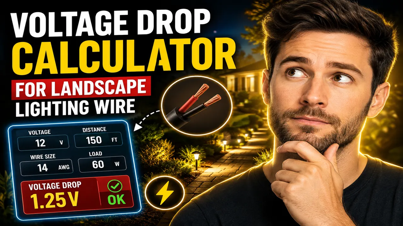
Voltage Drop Calculator For Landscape Lighting Wire
TL;DR Summary
The Voltage Drop Calculator For Landscape Lighting Wire estimates current, voltage loss, voltage-drop percentage, and the approximate voltage available at the fixture for a low-voltage landscape-lighting wire run. It is a planning estimate based on a two-conductor copper circuit and should not replace site-specific electrical design, equipment instructions, or applicable local requirements; no specific privacy behavior is provided for this tool, so avoid entering sensitive information.
About This Tool
The Voltage Drop Calculator For Landscape Lighting Wire helps you estimate how much voltage can be lost between a low-voltage lighting transformer or power source and the fixtures at the end of a wire run. Voltage drop matters more in low-voltage systems because even a small loss can represent a noticeable percentage of the available supply voltage.
This calculator is designed for common low-voltage landscape-lighting planning situations. You enter the system voltage, the total lighting load, the one-way distance from the power source to the load, and the copper wire gauge. The calculator then estimates the current flowing through the circuit and the voltage lost in the wire.
The tool supports common copper wire sizes from 18 AWG through 8 AWG. AWG means American Wire Gauge. A smaller AWG number represents a larger conductor. Larger conductors generally have a greater cross-sectional area and lower resistance, which can reduce voltage drop on a given run.
The lighting load is entered as W/VA. For this calculation, the load is converted to current using the supplied system voltage. For example, a 40 W load on a 12 V system corresponds to approximately 3.33 A. The calculator then uses the selected copper wire size and one-way distance to estimate voltage loss over the two-conductor circuit.
What the Calculator Tells You
- Load Current: The estimated current in amperes based on lighting load divided by system voltage.
- Voltage Drop: The estimated voltage lost in the wire, measured in volts.
- Voltage Drop Percentage: The voltage loss expressed as a percentage of the supplied voltage.
- Estimated Voltage at Fixture: The supply voltage minus the calculated wire voltage drop.
- Wire: The selected copper AWG size used in the calculation.
Who Can Use It?
This tool can help homeowners, landscape-lighting installers, maintenance teams, and anyone planning a low-voltage outdoor lighting run understand the effect of wire size and distance. It can also be useful when comparing different wire gauges before purchasing landscape-lighting cable.
How to Use
- Step 1: Enter the nominal system voltage supplied to the landscape-lighting circuit, such as 12 V.
- Step 2: Enter the total lighting load in watts or VA for the fixtures supplied by the run.
- Step 3: Enter the one-way distance in feet from the transformer or power source to the relevant load.
- Step 4: Select the copper wire gauge used for the run.
- Step 5: Review the estimated current, voltage drop, voltage-drop percentage, and voltage remaining at the fixture.
- Step 6: If the estimated voltage loss is too high for the equipment or project design, compare a larger wire size or a different circuit layout and recalculate.
Technical Explanation and Formula
The calculator uses the standard two-conductor voltage-drop relationship for a copper circuit:
Voltage Drop = (2 × K × I × L) ÷ CM
Where:
- Voltage Drop is the estimated voltage lost in volts (V).
- K is the copper resistivity constant, using 12.9 for this calculation.
- I is circuit current in amperes (A).
- L is the one-way wire-run length in feet (ft).
- CM is the conductor cross-sectional area in circular mils.
The factor of 2 represents the two conductors in the circuit: one conductor carries current toward the lighting load and the other provides the return path. The calculator therefore doubles the one-way distance internally rather than requiring you to enter the round-trip distance.
Current is estimated from:
Current = Lighting Load ÷ System Voltage
The percentage voltage drop is then:
Voltage Drop Percentage = (Voltage Drop ÷ System Voltage) × 100
Finally, the estimated voltage remaining at the fixture is:
Fixture Voltage = System Voltage − Voltage Drop
Wire Size and Circular Mils
| Wire Gauge | Approximate Circular Mils | General Effect |
|---|---|---|
| 18 AWG | 1,620 | Higher resistance than the larger listed sizes |
| 16 AWG | 2,580 | Smaller conductor |
| 14 AWG | 4,110 | Lower resistance than 16 AWG |
| 12 AWG | 6,530 | Common larger landscape-lighting conductor size |
| 10 AWG | 10,380 | Lower resistance for longer or higher-load runs |
| 8 AWG | 16,510 | Largest size offered by this calculator |
Worked Example
Suppose a landscape-lighting system supplies a total 40 W load from a 12 V source over a 100 ft one-way run using 12 AWG copper wire.
First, calculate current:
40 W ÷ 12 V = 3.33 A
Using 12 AWG copper with approximately 6,530 circular mils:
Voltage Drop = (2 × 12.9 × 3.33 × 100) ÷ 6,530
The estimated voltage drop is approximately 1.32 V. The percentage drop is approximately 11.0%, leaving about 10.68 V from a nominal 12 V supply at the calculated endpoint.
This example shows why distance, load, supply voltage, and conductor size all matter. A different wire gauge or shorter run changes the result.
Why Low-Voltage Landscape Lighting Is Sensitive to Voltage Drop
A one-volt loss is a much larger percentage of a 12 V system than it is of a higher-voltage system. As wire length and current increase, the voltage drop also increases. Increasing conductor size reduces the resistance represented by the conductor's cross-sectional area.
The layout of the lighting circuit can also affect the actual voltage delivered to individual fixtures. This calculator uses the selected load and one-way run as a simplified two-conductor circuit calculation. Real installations may distribute fixtures along the run rather than place the entire load at one endpoint. In those cases, individual fixture voltages can differ from the simplified endpoint estimate.
Why Use This Voltage Drop Calculator For Landscape Lighting Wire & How Our Calculator Beats the Competition
| Method | Ease of Use | Calculation Speed | Best For | Limitations |
|---|---|---|---|---|
| Toolhox Calculator | Enter four inputs | Immediate calculation | Quick low-voltage landscape-lighting estimates | Uses a simplified two-conductor copper model |
| Manual Calculation | Requires formula and wire data | Depends on the user | Checking individual calculations | More opportunity for input or arithmetic errors |
| Spreadsheet | Requires setup | Fast after setup | Repeated calculations and project worksheets | Requires maintaining formulas and wire data |
| Professional Engineering Software | Usually more involved | Depends on the software and model | Detailed electrical design work | More complex than needed for a simple voltage-drop estimate |
The practical advantage of this Toolhox calculator is that it puts the main variables for a simple landscape-lighting voltage-drop estimate into one calculation: supply voltage, total load, run length, and copper wire gauge. It is intended as a planning and comparison tool, not as a replacement for a detailed electrical design.
Assumptions and Limitations
- The calculation assumes a two-conductor copper circuit.
- The calculation uses the standard copper resistivity constant of 12.9 for the selected formula.
- The one-way distance is doubled internally to represent the outgoing and return conductors.
- The lighting load is converted to current by dividing load in W/VA by system voltage.
- The calculator does not model the exact location of every fixture along a distributed lighting run.
- It does not calculate transformer sizing, ampacity, overcurrent protection, connector losses, temperature corrections, or detailed installation-code compliance.
- It does not account for every possible conductor material, cable construction, power factor, or equipment-specific voltage requirement.
- The result is an estimate based on the information entered and the stated calculation model.
- Actual fixture voltage can differ because of transformer characteristics, connections, conductor temperature, load distribution, and other installation conditions.
- Users should follow the lighting manufacturer's instructions and applicable electrical requirements. Professional electrical review may be appropriate for complex, unusual, or safety-critical installations.
For a simple planning calculation, compare the result across several wire gauges and run lengths. A lower voltage-drop result does not by itself establish that a particular cable, transformer, connection method, or installation is suitable for a specific project.